
Applying Simple Principles
Set to soar
The main purpose of the plane is to stop itself falling to the ground, but in a specific way which makes it look pretty cool called flying. If the plane had any sentience it might start to contemplate the meaning of its existence and become horribly depressed at the circular argument it will find for an answer, but luckily it doesn’t and I don’t think far enough for that to be a problem so let’s continue.
Goal of contraption:
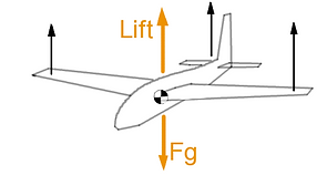
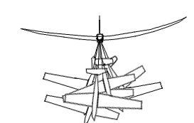
To keep the contraption in the air we need to create a lifting force to counter gravity. Since every atom in the plane has mass and is affected by gravity, we can see that the average force of gravity will act at the centre of mass. This means we want to have the wing right on top of the centre of mass so that we don't cause any moments (and make the plane roll or pitch or something) .
After this we can add other devices that actually WILL create moments, but we will be able to control these forces and therefore the moments they cause, giving us some control over how the plane will rotate and pitch and stuff.
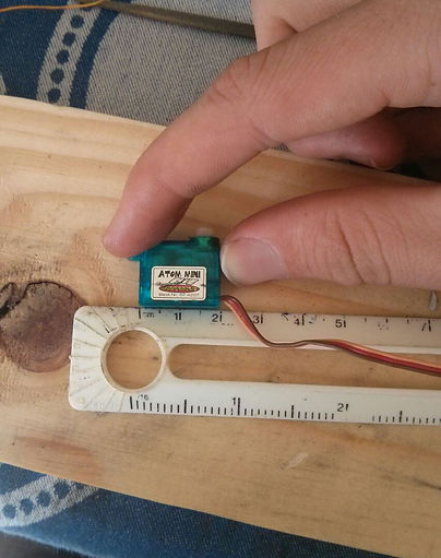
Since this entry is about building the plane I'm going to be very brief here and say I already chose the motors and electronics that will help us control these temporary forces. The motors are called servos and you'll see more about them later. The important thing is that there are 4 servos, one for each black force you see on the little sketch above.
Speed:
Since I’ll be flying it by eye, and I’ll be throwing it by hand, it’s operating speed should be something in the range of my physical abilities.
I can throw something the weight of a rock at around 20m/s so let’s assume the plane will be flying an average of 10m/s with an uppper bound of 30m/s since I think I’ll have a hard time controlling something that crosses a rugby field in under 3 seconds.
Strength:
This is a vague requirement but basically it should survive the force of me throwing it, of making sharp turns, and a direct strike from an unladen African swallow travelling at around 10m/s.
Aesthetics:
It shouldn’t look stupid
Other:
I plan to use a cleaned up fishing rod I picked up from an outdoor sports store for part of the fuselage (they just gave it to me since the lower half of the rod was broken, but the half I wanted was just fine). I also already have all the servos I want to use for it so I need to design for those.
Let’s ground some basic speeds and heights and things we expect it to handle:
Great. This means we can do some math:
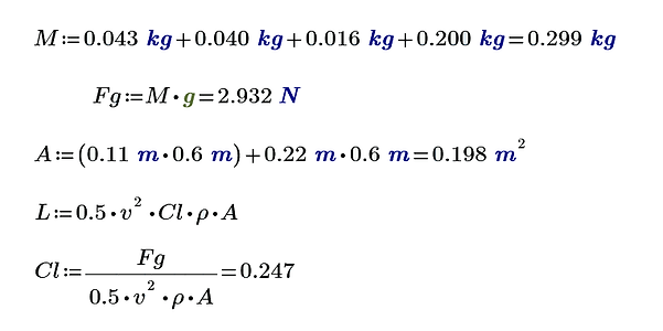
Since we said our main goal is to fight gravity, let's measure how strong it's going to be by making an estimate of the weight.
We will need:
Battery: 43g
Servos: 10g (4)
Receiver: 16g
Expected airframe weight: 200g
This gives a total mass of : 399g
This seems a bit light, but I'm going to leave it like that for now
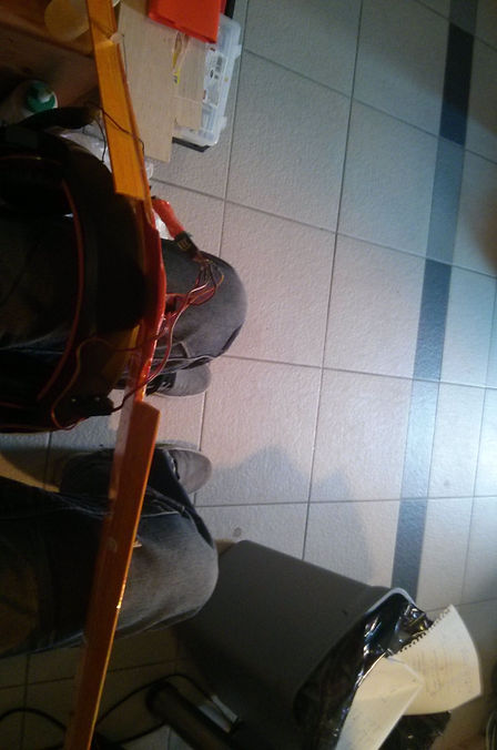
Now I’m going to calculate some speeds and expected heights from the throw. The basic technique is to grab the plane by its wing tip, twirl once to build some speed up in the plane and then let go.
Reading up a bit I should expect to launch this thing to a height of a round 40m. That means that the release velocity NOT considering air friction has to be:
Let’s say the wing will be about 1.2m long (I'm starting with a rough estimate based on the size I want) which gives it 0.6m from the body to the wing tip. Since the plane's centre of mass will rotate around me, I need to take the length of my arm into account too (measured at about 0.7m). This means for a mass centred around the point M, and me and the plane twirling like a pretty ballerina around point O, the total centripetal force exerted on the mass through the wing is calculated below.
This only accounts for the force exerted on the wing along its length. It's actually the easiest force to design for and not the one I expect to break the wing.
We need to figure out what the largest possible lift is that the wing will produce (and therefore the largest bending moment) since I definitely think that will be the one to cause the most trouble.
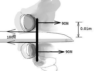
Unless I dive straight down to terminal velocity and pull up, I supsect the largest load on the wings will be right after I release the plane and pull up for the climb. The release velocity may actually be higher than terminal velocity and just for interest sake I'll check for that afterwards. I looked around and also watched some videos on the typical steep banking radii of these planes and it seems to be about 10m. Let me ilustrate:
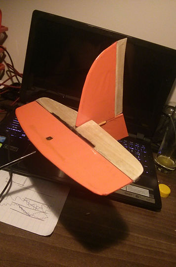
-
Orange arrows represent the forces we will focus on
-
Black arrows represent temporary forces we will create
Here we are going to look at what kind of structure and components we need to meet the criteria we discussed in the previous section.
Firt let's ask some questions we will need to answer in this section:
How big do the wings need to be? How wide? How Long?
Well, big enough to provide the force needed to do that 10m radius turn at 28m/s at least. The length I am going to to choose based on what I feel comfortable throwing. We also need to make sure they are big enoug so that the wing flies under minimal drag producing conditions, which will be shown later on.
Knowing the wing needs to have an airofoil shape, what will I make it?
Designing airofoils are very hard, and there are a lot of good ones out there, I will simply choose a very well suited one.
How thick does the wing need to be to carry the forces we worked out above?
Thick enough so that the material we make it out of is far from its strength limits, but ultimately the thickness will be determined by the airfoil, and I will have to make sure the strength requiremtns are met under those dimensions.
What will be the best way of building the wing?
This depends on the type of forces we see it encounters, but I plan on making a composite spar wing with thin balsa ribs.
How long does the tail boom need to be?
Long enough so that the tail plane can turn the plane using as little force as possible, but not to long as to unnecessarily increase the weight or the rotational inertia. Another thing that might be a problem is if the tail starts to wobble or vibrate, since the carbon tube acts as a nice energy storing spring. If it's short and stiff, we don't have to worry about that.
How big does the fins and control surfaces need to be?
There are general good practice guidelines on how to size up the tailplane, but in essence tailplane needs to stabelize the aircraft like a dart's fletching. A larget tail plane will mean the aircraft will be faster to point its nose true to the incoming airflow, and much faster to respond to controls, but also provides more drag. The horizontal stabelizer also needs to apply a force to counter the pitching moment caused by the wings as they produce lift which I will explain below.
The rest of the aspects in this section will be guestimates made from observation and some little experience in folding a paper plane before.
Requirements
For simplicity’s sake I’m going to choose the general shape of my wing now
My wing has the following profile:
I didn’t do any funny equations to get that planform (the top down shape of the wing) it just looks pretty right compared to most other wings I look at. There’s actually a special reason wings taper towards the tip and it has to do with the amount of drag the tip of the wing causes. A lot of complicated theories and effort go into reducing tip drag, and you can read up on it, but basically the fatter your tip is, the more drag you induce on it. This does not necessarily hold true at all air speeds but definitely at the low speeds I’m building the glider for.
Another important reason you want a small tip is to reduce the moment the wing will create where it's attatched to the body of the plane. So you want to make most of your lift as close to the body as possible, or you need to make a very strong wing for a very stupid reason.
Besides, it helps the plane meet the only aesthetic criterion I set for it.
You might wonder why I chose that line based shape, and the answer is because it will make the following calculations we are going to do much easier, and you'll see why.
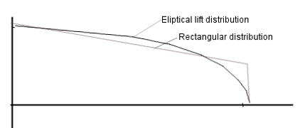
We now know that the ammount of lift an object produces as air flows over it is preportional to its top down surface area. So if you imagine the wing being chopped up into little slices and we calculated the lift each of those slices produced, we would see that it decreases as we go towards the tip like this:
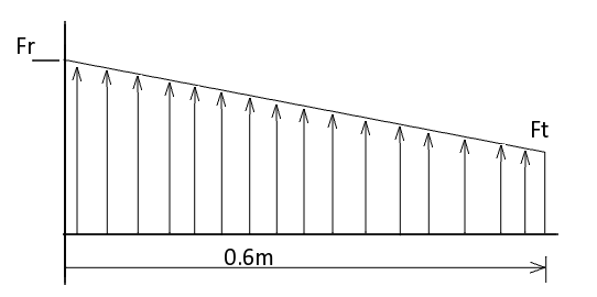
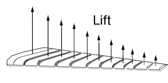
Now, mathematically we can chop this wing up into infinitely thin slices and add those infinitely many infinitely thin slices up to get a smooth graph that descibes the lift from the root of the wing all the way to the tip, calculus is beatiful. This is why I chose a straight lined outline for the wing because it means the graph for the lift will also be a straight line. But this only looks at lift in two dimensions, and this linear simplification is not how lift is really distributed across a wing, but I feel it's close enough for my hobby purposes anyway. The true lift distrubution is very close to elyptical, where the vortices created by the wing tip and disturances by the body at the wing root is taken into account.
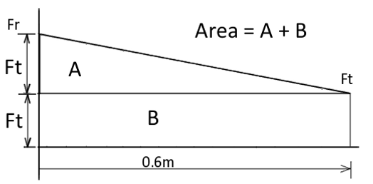
We don't know yet what Fr or Ft is, but we know the one will be half the other.
Now, since we chose the tip to be half the width of the root, we can easily see that the amount of force a slither of wing at the tip will produce (let's call it dFt) is half the ammount of force a slither of wing will produce at the root (let's call that force dFr).
So, if we know now what lift each little slither of wing will produce, that meens if we add them all up we will get the total lift produced by the wing.
What we also know is that we need to produce at least 24N of lift to pull the aircraft into that tight turn.
Before we go further please note:
We might get a very weird answer from the following method I will try, and if the answer is nothing what I expected then I'm going to try another method. I say this because if the only criterion we're taking into account at the moment is at the wing's most extreme state of flight we may end up with a wing that's only good at meeting those criteria and not very good at normal flight. There are other aspects we will take into account after this.
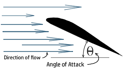
As I was saying, we need the wings to give us 24N of lift traveling at 28m/s. One important thing to note about wings are that they can give different amounts of lift depending on how much you turn their tip up against the incomming air. This is known as it's Angle of Attack (since it's the angle the air attacks it at).
As an example, think of holding your hand out a car window and tilting it so it gets pushed up by the wind.
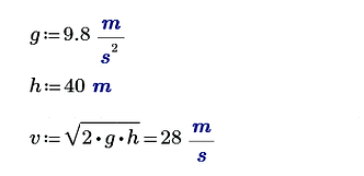
where v is release velocity with magnitude 28m/2
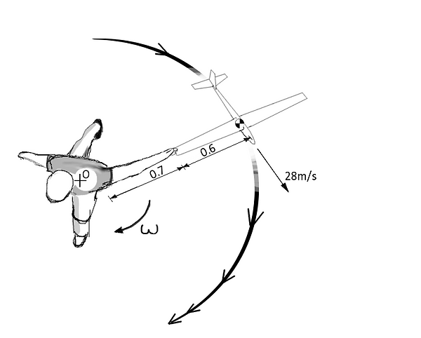
This diagram lays out the situation for us
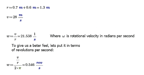
This means right at the point of release, I will spin around twice in about a seccond. But this still doesn't tell us what kind of pulling force will be exerted on the wing, so the following equation will tell us:

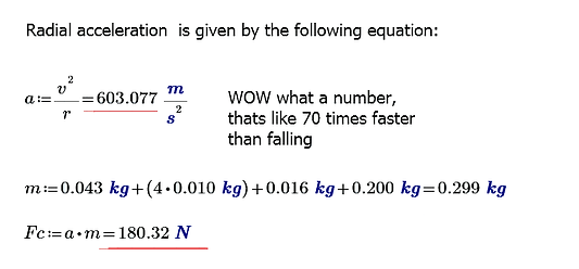
180N. That's quite some force! That's like hanging 9 bottles of coke from the wingtip (vertically of course).
Even though this was a simplification of the situation (compitition throwing speed conditions), it was a conservative one so if we design for this we are still safe


This means the force needed to turn the plane around that circle is given by the same equation we used before:
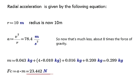
24N doesn't seem so bad, it's like hanging 8 planes from this one while it flies.
There are a lot more forces going to act on the plane, but I'm not building a passenger plane and I don't have to compete for cost or efficiency. I also don't see the tailplane I build breaking under any normal flight conditions so I won't concentrate much effort in proving its strength.
Design
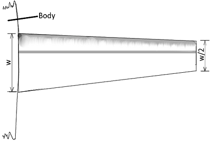
Where the thickest part of the wing runs straight and the width decreses from w to half of w:
Let's look at the equation we are going to use to predict the lift the wing will produce:
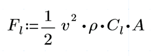
This equation misrepresents the complexities of earodynamics, but all the very complex work is usually summed up for us in that one little Cl Term. It basically describes how good an object is at creating lift. Whenever I talk about the Coefficient of Lift, I mean that value. It doesn't mean much by iteslf, but indicates how much lift we should expect to get for a certain set of flight conditions.
We also see that v (velocity) has an exponential effect on the force, while all other terms have a linear effect.
Now we can go on to find the wing size we need at those conditions.
To find the sum of all the little lifting forces produced by the slithers of wing, we just have to integrate along the wing length with and equation that describes the distribution of lift. Even more simply, we just need to find the area under the graph. The following drawing will show how:
For a while now I’ve been fascinated by a class of remote controlled glider known as a DLG. DLG stands for Discus Launched Glider and is basically just a description of how you get the thing up in the air.
What I like about them is the work involved in making them strong enough to handle the launch, and yet light enough to get as much height as possible. Since they have these two properties they’re also able to handle very agile movements and acrobtics. It also looks awesome when you launch them.
Project Plan:
-
Obtain some info about how these things operate from videos and forums.
-
Design my own glider.
-
Build that glider.
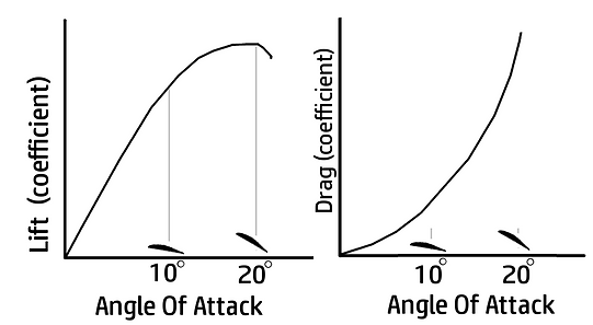
The problem is that as you increase the angle, you not only increase the lift, but the drag goes up too.
SO, you need to be carful to not design a wing only at the maximum lift it can produce (small highly loaded wing), because the plane will slow down very quickly. Here are two simple graphs showing how the two properties are related:
Now that we know that, I'm going to add that when we pull the nose of the aircraft up after the throw we will most likely be opperating near the top of that lift graph's highest possible point. The drag will also be pretty high but we won't worry about that for now since the turn is going to be very quick.
So let's proceed with a typical Lift Coefficient value you can expect from a glider airfoil at that point.
Most research I did put that at around 1.2
Note how Ft only represents the ammount of force produced, not the actual width of the wing.
I will now manipulate a few equations to give me an estimate of the tip size I need:

The lift equation with the formual for the area
where area = (w*l) + Half w * l
Substituting in my wanted length
Ammount of force onee wing should produce, the density of air, lift coefficient, and velocity
This puts the wing tip at about 0.12 m long which is a very reasonable estimate. This also means the root airfoil length should be 0.24m
Now that we have decent wing size for managing our sharp banking, let's see how well it will perform in normal gliding flight. To be honest I think I should have done this calculation first, but I was expecting a very strange answer from the above equation (something much smaller maybe) so that I could do this and say "much better", but I'm happy with it so nevermind.
What we need for a good gliding flight is enough force to counter gravity and as little drag as possible. Remember how you can make a small wing generate lots of lift by increasing the angle of attack but at the same time its drag goes exponentially higher?
Well what we want to see is what kind of drag we will get at a certain lift coefficient of the wing, and if it seems horrible, we may need to incrase the size of the wing, but I have a feeling we will be fine

The tool I will use to see what kind of drag to expect from my wing is a program that a lot of model aircraft builders use called XFLR-5 and was introduced to me by a brilliant aerodynamycist I had the privilge of working under during some vacation training I did. It's a program that takes in an airfoil at certain conditions, and then does a whole bunch of math at different angles of attack. One of the graphs it gives you back is one that shows lift vs drag, and that will be the one I'm going to look at here.
What we'll need to give the program is the follwing:
1) Reynold's Number of air flow over our wing. (Look it up under the principle list)
2) An airfoil we want to evaluate.
Doing a lot of searching on the web I came across two very popular airfoils that people seem to use for DLG sail planes.
The one is the HM-51 that looks like this:
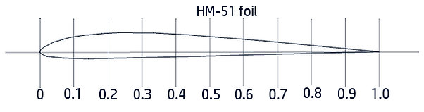
THIS IS A ROUGH SKETCH DON'T USE THIS AS A TEMPLATE
The other one is the AG38 that looks like this:
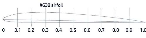
You may ask why I'm not designing my own airfoil and the reason is that it's probably one of the most difficult forms of art man has come up with. If there are magicians in this world, earodynamisists that know how to design airfoils are amoungst them. Just looking at these two wing profiles you can barely see a difference, but every subtle change in curvature or difference in angle changes the way air and flows and follows the surface drastically.
I chose to use the HM-51 airfoil because it's slightly thicker and since I plan on building the plane out of balsa and other squishy stuff I want all the strength I can get.
What we need now is the Reynold's Number for the flow of air over our wing.
I will use the average air speed and average chord length (distance between leading edge of wing and trailing edge) of the wing and use a value for the viscosity of air I got off the internet:
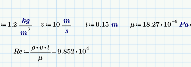
Viscocity of air:
Average flight velocity
Note how the Reynold's number has no unit, it's purely a number that tells us how turbulent the flow is in these conditions.
Sticking this into XFLR-5 we get the following data for angles of attack ranging from -5 to 20 degrees:
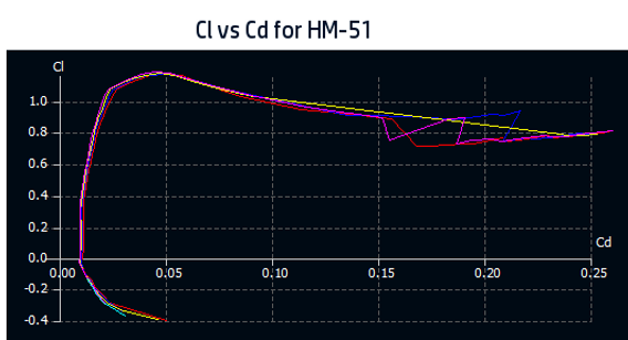

If it's not clear what these graphs show us imediately, that's ok I also didn't quite get it at first.
The first one has a bunch of connected points where each point represents a certain angle of attack. The second graph shows us the lift coefficient at different angles of attack (alpha) and we can sort of deduce that the two peaks on the graphs correspond to eachother since both Y axes tell us the coefficient of lift
of Lift. Don't worry about the different colours, you can think of them as different speeds.
Something cool to note about the graph on the right is that the wing wtill produces lift even at negative angles up to about -3 degrees by the looks of it. This is a property of geometry and fluid dynamics, not some psudoscience magic (That's what I was told).
This is all very nice and pretty, but how do we use this?
Well first let's see what kind of Lift Coefficient we need to keep the plane in the air at 10m/s and then we can find that lift coefficient on the graph and therefore the corresponding drag coefficient.
So to maintain level flight we need a coefficient of lift of about 0.247
Looking at our Cl vs Cd graph, this corresponds to a coefficient of drag of about 0.012
What does this mean? Well this will help us figure out the ammount of drag the aircraft will experience and give us an estimate for how fast it will loose speed and therefore altitude (since it has to dive to keep the speed up).
Let's see if we can expect a decent value for a glide slope (ratio of foreward movement to drop in altitude). I expect it to be fairly ok since a wing thats about 20cm wide looks like a standard size on these models.
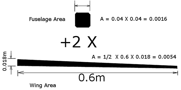
For this we need to work out the total frontal area of the aircraft and use the drag equation to calculate the drag force on the plane.
The frontal fuselage area I'm going to calculate as a semi square the size of my expected fuselage. The wings will have dimensions specified by their airfoils which for the HM-51 having a thickness of about 8% of its length. This gives us a root wing thickness of 18mm.
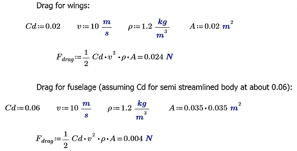
Now we can calculate the drag. I will use the coefficient of drag that the graph predicted for the wings and one I found on the internet I think most clsely matches the shape of the body I'll build:
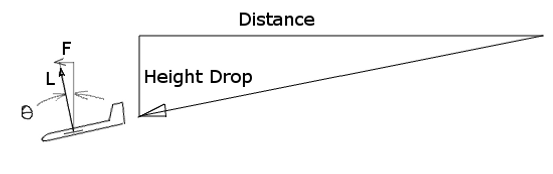
To keep the plane moving forward, we need to tilt the force vector of the lift slightly over till its horizontal component is equal to the magnitude of the drag force. This diagram shows what I mean:
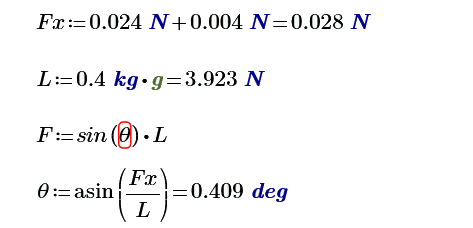
Less than a degree?? This does not seem right at all. That's a glide slope outperforming all modern full scale competition sailplanes.
Since I can't find a lot of information on how glide slopes are predicted. I'm going to assume that it won't be absolutely terrible and since I don't have a lot of time to spend on this project I will move on.
I might come back and edit this part once I know, and I'll compare the predicted and real values.
Here is some more information and things I have before we go to the drawing part:
-
I have an old carbon fibre fishing rod I will make the boom of the fuselage out of.
-
I don't have any way of molding shapes, so any composites have to be layed over something or be simple flat shapes and layups of things I can find in my room, like a toothbrush or spoon.
-
I want to use as much balsa wood as I can because balsa is cool.
Since I have a basic wing shape, I have a set wing thickness that's needed by my chosen airfoils, and a general idea of what I want the thing to look like, I'm going to go ahead and draw up a rough design for the plane.
The rest I can do using the TSAR meathod. This method was often implimented by a brilliant engineer I had the pleasure of working with for a short while. It stands for That Seems About Right.
It seems like a leap, but really the most important things have been calculated for a model aircraft and a designing process is a highly itterative one, so I'm going to start with my first iteration.
Drawing

Plane Drawing
Some things to explain about the above drawing:
-
Holes are cut in the tail and fin to remove weight, the corners rounded to reduce stress concentration and cracking.
-
The wing is just over 1.5 times the length of the body. (Based on TSAR and ratios I looked up).
-
The top and bottom of the spar (bar that carries the force produced by the wing to the body) is covered top and bottom by a thin carbon spar cap I found at a hobby store, but there will be much more detail about this below.
-
The centre of the wing where the two halves join will get some carbon reinforcement (the thick triangle)
-
The wing's thickness is purely dictated by the airfoil, so I need to design for those dimenstions.
-
Plan to use push pull rods to controll the fins at the back.
-
The Body will be a simple balsa box with the boom mounted in the back. This part I feel comfortable improvising, so I don't have much info about that for now.
-
The tail and fin will be thin balsa with strips of glass or carbon fiber layed on top in certain places to reinforce them.
-
The size and shape body was mainly dictated by the size of the components and servos I had
-
How I chose the position of the wing and the length of the tail boom will be shown below
Wing strength predictions:
Since the wing will carry a lot of force, I want to make sure the current plan I have for it will hold up. To do this, let's first see again how the force is distributed through the wing, and how we expect it to translate that force into the body and lift the plane:
To figure out how long the tail boom of the plane should be was an approximation based on how large I wanted my wings to be. Like I said in the seccond bullet it was mostly based on how I felt the plane would react to different tail lengths. A shorter tail would mean sharper turns and faster pitching rate but would be hard to fly, while a longer one would fly smoother and more efficiently but have a rather low pitching rate. I figured the sharpness of the plane's turns has more to to with how large your elevator is and how much you rotate it, but having a large tail boom definately increases your turning circle and decreases the nessisarry size of your tailplane.
If we integrate the lift graph (simply add up all the force made by each little part in the wing) we can find the distribution of shear stress:
From the shear stress we can integrate to find the distribution of the moment the wing will experience:
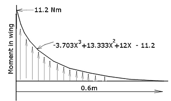
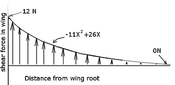
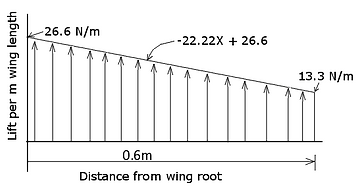
Here's the lift force graph we calculated:
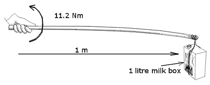
11.2 Nm of torque is about how hard you have twist your hand to hold a box of milk hanging from a pole a meter away
Wings
Wing Lift
These graphs help us a lot in visualizing the way forces and stresses build up in the wing, you should note on the shear force diagram that the total force added from the tip to the root (from 0.6m to 0m on the graph) equals to 12N which when we have a wing on either side adds to the 24N we wanted to be able to accelerate the plane through its tightest turn.
We can see (now not just based on intuition) that the wing can have a thin, weak tip since there isn't much force that has gathered in it yet, but as we move to the root, the wing will need to become thicker and thicker to carry the accumulated load of the lift till it can finaly dissepate into the body and counter the weight of the plane body.
If you can remember, we already chose the length of the wing root and wing tip, as well as the airfoil we will use which means we are stuck with a linearly tapering wing that goes from being 18mm thick to 9mm thick.
Since I am building the plane out of balsa, the simplest and easiest structure that will handle these forces are a few balsa ribs that are covered in a film to give us the wing airfoil, and a strong spar running through their middle. The force (due to a pressure difference on the top and bottom of the wing) will be translated through the ribs from the film, into the spar wich will carry it to the body.
As such, I am not going to worry too much about the ribs, I will concentrate on the spar.
To root
To tip
I'm going to make a guess (based on a little experience) and say that our biggest problem in the wing will be the moment in the spar. The shear force maxes at 12N which, when spread over a tiny surface, is still a lot of stress. But let's look at the stress the moment will cause at it's maximum point (at the root).
First using a spar made from the same material throughout (solid piece of wood or something)

The stress the material will experience varies linearly from a maximum value at the top and bottom, to zero in the centre. The amount of stress is directly related to how far we stretch the material, since the most stretch occurs furthest away from the centre, that's where the maximum stress will be.
From this graph we can sort of see that is we want to improve any material properties its best we do it at the surface of the top and bottom where the most stress is.
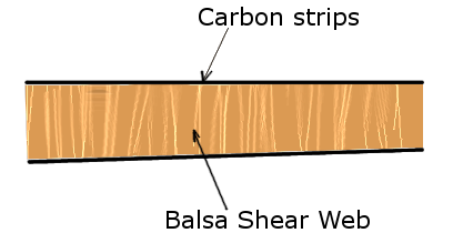
This also means that if we use a stiffer material at these points, it will take the brunt of the load, since it doesn't want to stretch at all, and leave very little for the centre to worry about. As an example, here is the stress distribution of a bar that has very stiff top and bottom pieces glued to a squishy centre piece:

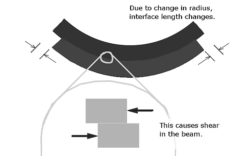
Something you may not see from the design above, is that the balsa we will use as the core of the spar will have its grain run perpendicular to the length of the spar. The reason is very interesting, and I'll try and give a simple explination. We have a very stiff upper portion of the spar being complressed and another stiff portion at the bottom being stretched, but there must be some interface where the compression counters the tension and cancels out. If our beam was made of lots of slabs that weren't glued together, and you bent it, they would wach try and maintain their original lengths, but be forced to have the same curvature. They would slide past each other where they touched. However, if you glued them together, they will push and pull on eachother and translate the force. Hopefully the follwing image makes that a little clearer:
What does this mean? Well, if we know that wood has a very good resistance to shearing off against its grain (sliing wood fibers along eachother is easier than breaking through them), then if we orient the grain perpendicularly to the shearing force it will encounter, it will be much stronger.
This image shows the general spar construction idea:
So, we now have details about the forces in the wing and the geometry of its construction. I will now perform some simple strength calculations and see what I get.
First and easiest, a simple calculation to see if the wing can handle the vertical shear force of 12N. I will assume the wood doesn't resist this force at all, and it's only the carbon strips that take it.
I am going to make a good guess at the size of wing I need. It will be based mostly on what I'd feel most comforatble swinging around myself and what size I want to carry around.
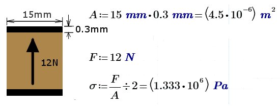
Shear force in the carbon strips is 6.667 Mpa, and the maximum shear the carbon can take is apparently around 90 Mpa (assuming this is across the grain of the fibers) . So this gives us a safety factor of over 60, great.
Next I will calculate the normal stresses on the spar where it will be the worst; the top and bottom surfaces. The normal stress is the stress the spar experiences along its length. It causes the compression and tention that will crush or pull appart the fibers. I will assume that no contribution is made by the balsa and only the carbon takes up the force. For this I need to calculate my seccond moment of area (how good a shape is at resisting bending) which will just be the two reinforces layers of carbon on the wing.
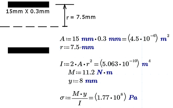
Since the tensile trength of carbon laminate with the force directly along the fibre orientation is 600Mpa according to a textbook and a site I found on the internet, this gives us a safety factor of 3.4 excluding the contribution the balsa or glass would make even if it was very small.
Great, so it looks like the wing will hold up just fine.
Right now I don't see what I could improve imediately. Any further improvements would require a lot of itteration and calculation, and will only make a huge difference if several of them were added together. I want to start building, and as I build I'd most likely run into problems and work around them.
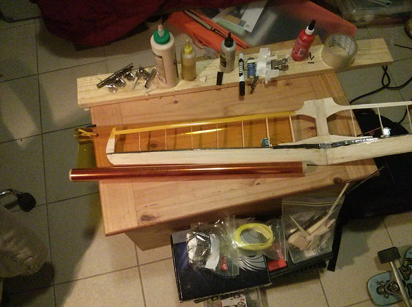
Construction
I think I'll start with the body first, it should be the easiest.
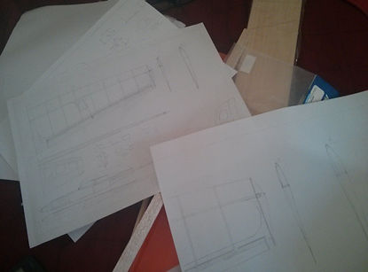
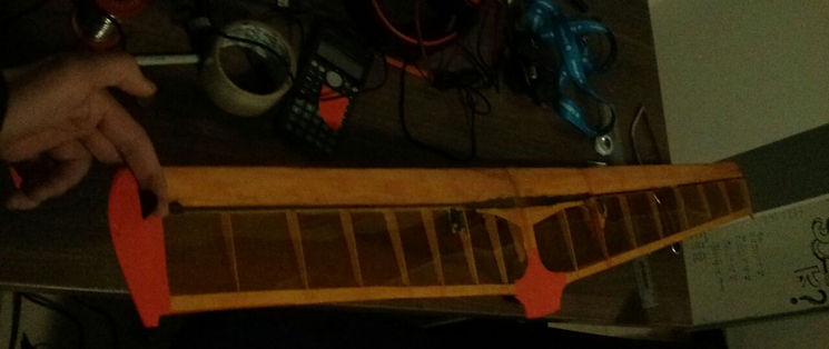
First I photocopied the design and scaled it by two to get some paper templates for parts
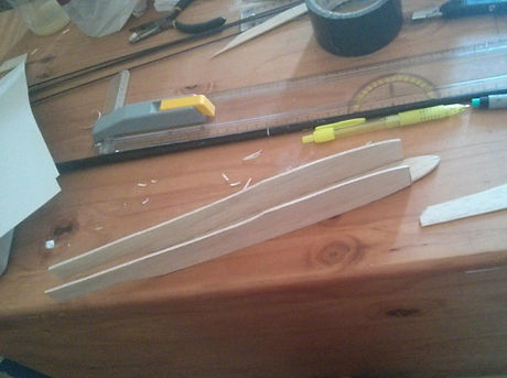
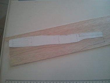
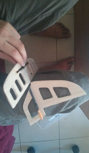
One side of the fuselage I traced onto the balsa, I used a 1.5mm sheet.
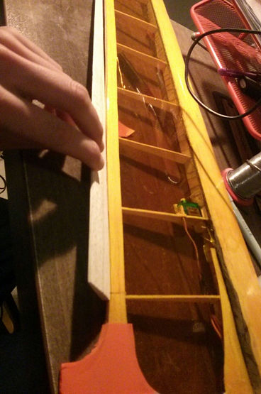
Tacked the sides to the base with superglue and shaped the nose block out of pieces of balsa I glued together.

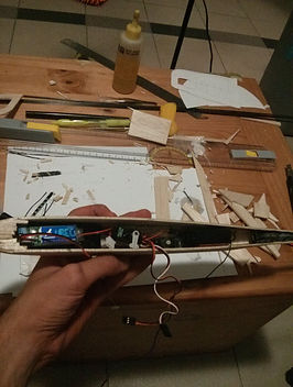
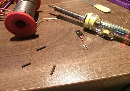
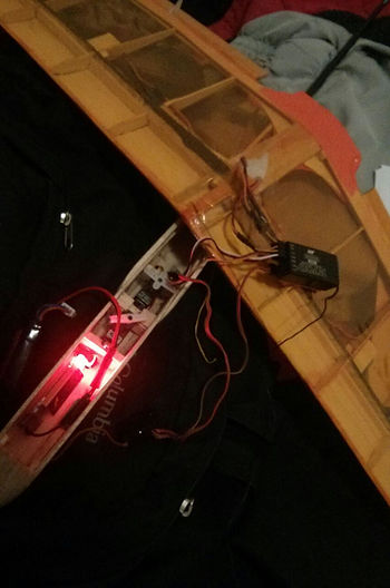
Inside of the fuselage got two strips of carbon, and I chopped up some carbon mat into a heap of loose fibers which I mixed with resin to make a strong and light filler to hold the boom (half a fishing rod) in place.
Cut out the tailplane pieces and put one thin layer of carbon chord on the top and bottom of the horizontal stabelizer.
The elevator has to go around the fin, and since only one side will be twisted by the control horn, the torque has to be transmitted to the other side. I took some carbon tow and wrapped it round a small dowel I used to link the two pieces then places these two clamps on till it cured. It made it very stiff and gave no play on the other side.
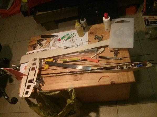
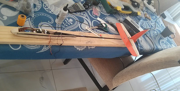
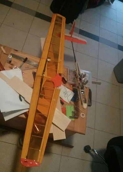
Plopped everything I had so far into and onto the fuslage, to see how far it is.
Finished covering the tailplane pieces, I still need to heatgun the plastic so it shrinks on properly.
Mosquito repellent
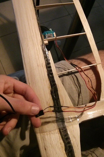
By the looks of things so far, I'm going to have to use a pull-pull system for the tail since I don't see how I'm going to fit in a push rod system. The reciever comes too close to the entrance of the tail boom to get a push rod around it.
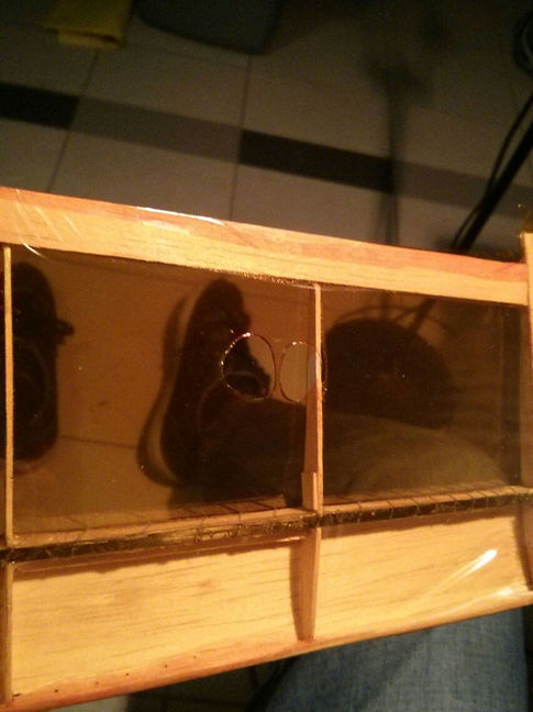
I printed out the airfoils and scaled each one including the place where the spar will fit. Then traced them onto the balsa. The three inner ribs were from 1.5mm balsa and the outter ribs are from 1mm balsa.

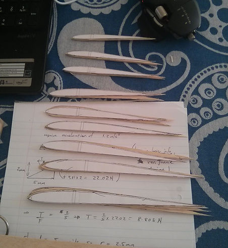

Finished cutting the ribs. I glued the airfoil templates to them with prit and will sand them down till they match the lines exactly
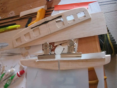
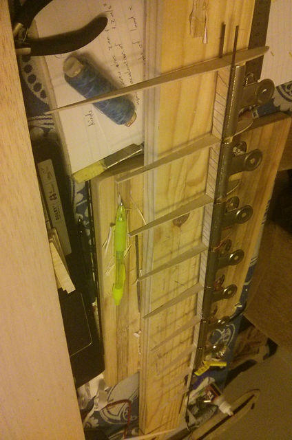
I forgot to take some pictures at this point, so far I cut the little vertically grained strips of wood that go between the ribs to act as the shear web, and in this picture you can see the two carbon strips and centre wing assembly being clamped till the resin cures.
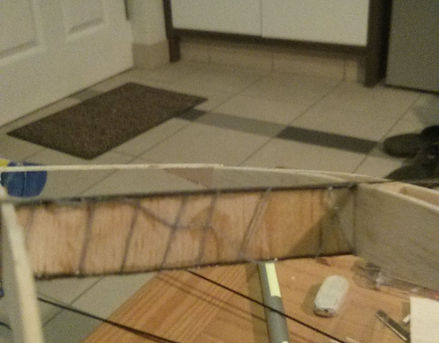
The resin I used was Smooth-On laminating resin that I had from a previous project building fiberglass backed longbows. It worked very well since it was tacky and allowed me to straighten out the spar before leaving it to cure.
Here is a bad close up of the spar construction. The thread was just wrapped around to keep everything in place while I placed the clamps on.
Here's both halves of the wing placed together after I added some balsa to the trailing and leading edges.

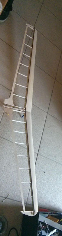
Glued the two halves together, but it still need to get its reinforcing glass and carbon strips.
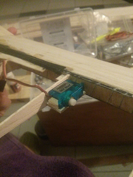
Adding bits of servo wire extension to the little wing servos
Making the little mounts for the wing servos. I'm just going to glue them in.
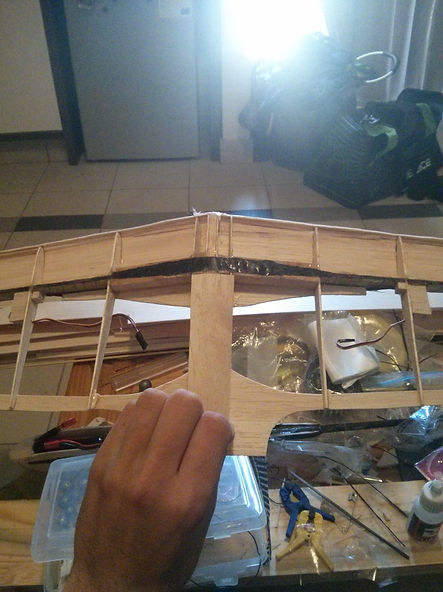
Here you can see the reinforcement and the wing joint on the bottom
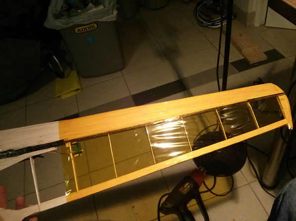

I'm going to start covering the wings. I got some clear and thin orange covering film because I like the look of the wood through it.
Placing the wing on the film and tracing a rough outline with marker
I spent nearly an hour trying to iron on this film and it never wanted to stick to the balsa, and I wondered seeveral times is there was a thin protective sheet over the adhesive layer but I couldn't seem to find it or pull it off.
After becoming a little frustrated I took two pieces of tape and stuck them on either side of the film, and when I pulled, suddenly a very thin clear protective covering peeled away, so I proceeded to cover the wing feeling chuffed at having won.
There were a lot of wrinkles in this area and I held the heatgun over the film too long. The film suddenly grew two massive holes as I obviously didn't really know what I was doing. I cut the piece out and ironed on a patch over the hole.
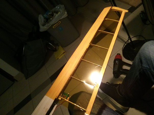
I made several mistakes while covering the wing since it was the first time I've tried this, but some things should have just been common sense such as making sure every surface the film would touch was free of any bumps or step changes. The film did a very good job here at pulling taught and trying to hide my sloppyness.
I seems the film doesn't like to stick to glass laminate, so there were some wrinkles at the centre of the wing, but I was fine with that for now.
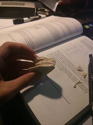
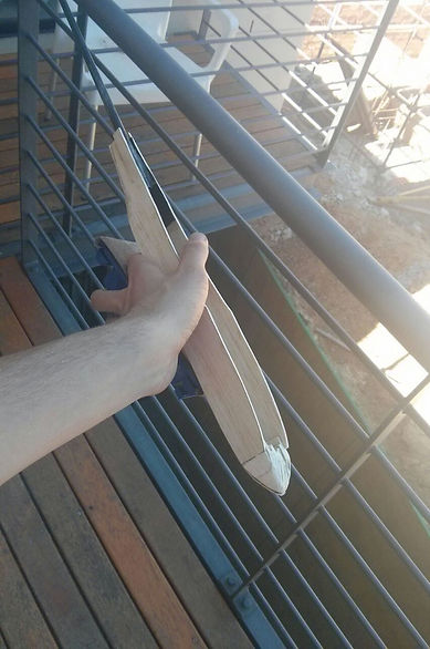
I made a finger tab to throw the plane by layering a few pieces of carbon and placing every textbook I had on top of it to compress the layup while it cured. The tab was very strong, and I glued it directly to the spar of the wing with some reinforcing. I think I could have cut it a bit thinner, But I wanted the extra surface area for the glue. I covered the throwing tip and some uncovered part of the trailing edge with the solid orange film I had.
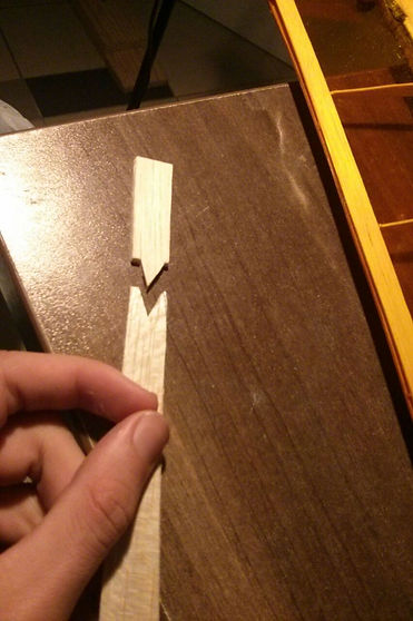
I had some triangular balsa pieces for making ailerons, but I needed to extend them a little to reach all the way. I cut a V slot and key to increase the bonding surface area.
Here you can see the glass fibre and carbon along with the added servos
One more thing I just want to calculate quickly is what kind of thickness I should make the finger tab I will attatch to the wing so it doesn't break, and also how much reinforcement I should add when gluing it in. I'll take the maximum tensile strength of carbon as 600 Mpa again with a safety factor of 1.6
This diagram shows the load the tab will be under:
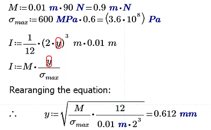
So I should make the tab just a little less than a millimeter thick.
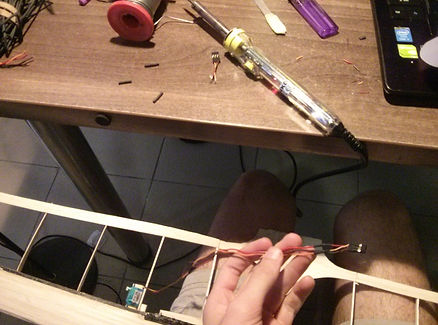
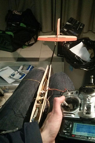
After taping on the ailerons and attatching the control lines to the servo arms, I could test out the controls for the first time:


I used some bow chord from one of my longbow projects since the dacron stretches very little and is very strong.
To fit the reciever in will all the servo wires I needed to take it out of its cover.
Full right ailerons
Full left rudder
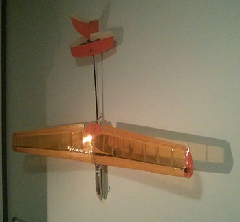
Here are the test flights:
Testing
For these tests I didn't go for endurance, I dived and shook it around in the air to get a feel for what it does. I hope to have some thermal soaring videos up soon. A lot still needs to be done with the plane (filling in the aileron gaps, smoothing out some of the wing covering, covering the fuselage and fixing something in the elevator etc...)
Where v = 28m/s and r = 1.3m
Release
Project Background:
To Monique, so she can understand how I made her plane